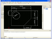
 QCAD è un CAD 2D molto semplice, rilasciato sotto licenza GPL. Permette la creazione e la stampa di disegni 2D.
Qcad è un software adatto a realizzare in 2D un disegno tecnico che rappresenti un manufatto, una parte meccanica, la pianta o gli interni di una costruzione.
Dotato di una interfaccia amichevole, è di facile comprensione e può essere usato in breve tempo anche da utenti non specializzati.
Gli strumenti necessari al disegno sono rintracciabili tra i menu e, con l'aspetto di semplici bottoni, in opportune barre generalmente posizionate a destra della finestra di lavoro.
Il disegno può essere realizzato su diversi livelli, ad esempio su un primo livello si può tracciare e mettere in misura la struttura dell'oggetto, su un secondo livello potrà essere eseguito il disegno finale, che verrà quotato su un terzo.
I livelli possono essere visionati o stampati separatamente o in gruppi selezionabili sovrapposti. Una terza finestra funziona come una console che permette di vedere le coordinate dei vari oggetti o di scrivere righe di comando. Si possono utilizzare font diversi. I disegni vengono salvati in formato .dxf, formato testuale che può essere letto da tutti i software tipo cad.
Il programma è sviluppato dalla Ribbonsoft ed il suo principale sviluppatore è Andrew Mustun.
Fa uso delle librerie dxflib dello stesso sviluppatore e delle librerie Qt della Trolltech.
Sul sito delle Ribbonsoft viene messo a disposizione il codice sorgente del programma in una versione non aggiornatissima (la Community Edition), non disponibile per Windows, che impiega le Qt versione 3. Il codice viene rilasciato sotto licenza GPL.
Se si vuole avere una versione binaria aggiornata che fa uso delle librerie Qt versione 4 è necessario acquistare una licenza, altrimenti ci si deve accontentare di una delle demo disponibili sul sito, che dopo un certo lasso di tempo si chiudono automaticamente. Se invece non ci sono particolari esigenze è sufficiente compilare il codice sorgente smanettando un po' con gli script di installazione e facendo a meno delle ultime novità.
Il formato dei file che utilizza è il DXF (versione 2000) anche se non ne supporta tutte le estensioni, in particolare non supporta i layout. I file si possono esportare in vari formati, ma non in VRML e in SVG.
È possibile stampare i disegni utilizzando le stampanti di sistema (in particolare sotto GNU/Linux supporta senza problemi CUPS). È inoltre possibile stampare i disegni su file postscript, opzione che permette di importare le tavole all'interno di programmi di impaginazione.
Screenshots:
QCAD on Mac OS X.
Le versioni disponibili per Linux:
Versione 2.2.2
Ubuntu 5.1, 7.04, 7.10, 8.04, 8.10, 9.04, 10.04; openSUSE 10.0, 10.1, 10.2, 10.3, 11.0, 11.1, 11.2; Fedora 2, 3, 4, 5, 6, 7, 8, 9; Debian GNU Linux 3.1, 4.0; Mandrivia 2006, 2007; Mepis 6.0; Knoppix 3.3, 3.4, 3.8, 3.9, 4.0; SUSE 9.0, 9.1, 10.0; Redhat 9.0; Mandrake 9.2, 10.0, 10.1; CentOS 4.3; Linspire 4.5, 5.0; Puppy 1.0.5; UHU-Linux 1.2; Xandros 2, 3; many other Linux distributions
Features:
- Multi-document interface
- Layer support
- Block support (grouping)
- Integrated part / symbol browser
- 24bit Colors
- 24 different line widths
- 19 line styles
- 35 CAD optimized fonts
- 200 undo/ redo levels
- Clipboard functions (copy, cut, paste)
- Rotate, scale, flip while pasting
- Supported units:
- Metrical: Nanometer, Millimeter, Centimeter, Decimeter, Meter, ...
- Imperial: Inch, Foot, Mile, Microinch, Mil, Yard
- Other: Angstrom, Micron, Astro, Lightyear, Parsec
- Supported file formats:
- DXF R12 and DXF 200x (reading / writing)
- BMP, JPEG, PNG, .. (import and export as bitmaps)
- SVG (export)
- High quality PDF (export)
- Printing
- Printing to scale (e.g. 1:2, 1:100, ..)
- Print preview with paper selection
- Construction
- Points
- Lines
- with two points
- given absolute angle
- horizontal / vertical
- rectangles
- parallels
- bisectors
- tangents
- orthogonal
- given relative angle
- regular polygons
- freehand lines
- Arcs
- center, radius, angles
- three points
- concentric
- adjacent to existing entity
- Circles
- center, circle line point
- center, radius
- two opposed points
- three points
- concentric
- Ellipses
- center, two points (minor and major axis)
- center, two points, start angle, end angle
- Splines (NURBS)
- degrees 2, 3
- closed, open
- Polylines
- line and arc segments
- add / delete nodes
- trim segments
- delete all nodes between two given segments
- create polylines from existing segments
- create equidistant polylines
- with rounded or sharp corners
- Texts
- fonts: ISO, ISO cursive, Courier, Romans, ... (35 CAD fonts included)
- alignments: left, right, centered
- vertical alignments: top, bottom, middle
- unicode support (Japanese, Chinese, German umlauts, ...)
- Dimensions
- aligned
- linear
- horizontal / vertical
- radius
- diameter
- angles
- arrows (leaders)
- use arrows or architectural ticks (45 degree lines)
- Hatches
- 40 patterns (extensible by the user)
- adjustable pattern scale and angle
- solid fill (color fill)
- Raster images (bitmaps)
- insertion of bitmaps
- adjustable scale, rotation angle
- Modification
- move
- rotate
- scale
- mirror
- move and rotate
- rotate and counter-rotate
- trim to entity
- trim by amount
- bevel
- round
- divide
- divide 2 (remove segment)
- stretch
- edit geometry (numeric)
- edit attributes (color, line width, line pattern, layer)
- exploding texts / dimensions / hatches / ellipses into atomic elements
- edit texts
- delete
- move to background / foreground
- modify properties or single or multiple entities with property editor
- Element selection functions
- all / nothing
- single elements
- rectangular ranges
- connected elements (contours)
- elements intersected by a selecting line
- invert selection
- select layer
- Snapping functions
(used to position the mouse cursor to an exactly defined location) - free
- snap to grid
- snap to endpoints
- snap to center points
- snap to middle points
- snap to intersections
- location defined by entered co-ordinates
(relative/absolute/cartesian/angular) - auto snap
- Measuring functions
- distance between two points
- distance between an element and a point
- angle between two lines
- total length of selected entities
- polygonal area / circumference
- Zoom functions
- redraw
- auto zoom
- zoom in / out (mouse wheel or buttons / hotkeys)
- panning (middle mouse button)
- window zoom
- zoom to selection
- Part library
- over 4800 CAD parts included (screws, nuts, symbols, ...)
- insert parts into the drawing
- adjust angle and scale
- extensible with user defined drawings and symbols
- Misc features
- adjustable dimension unit format and accuracy
- modification of existing CAD fonts and creation of new fonts
- ECMA scripting interface with integrated development environment (IDE)
- integrated user reference manual
- isometric projections (pseudo 3d)
- User interface translations
- Bulgarian
- Chinese
- Czech
- Danish
- Dutch
- English
- Estonian
- French
- German
- Greek
- Hungarian
- Indonesian
- Italian
- Norwegian
- Polish
- Punjabi
- Portuguese (BR)
- Russian
- Slovak
- Spanish
- Turkish
- Welsh


